
Image stabilized binoculars reduce visible shake by detecting motion, calculating a correction, and changing the optical path with a controlled moving element. The important detail is that the moving element is not universal: current systems include gimbal-mounted prisms and lens-shift designs, while some manufacturers describe control behavior without publicly identifying the internal moving component. Stabilization can make a handheld view easier to hold on a subject, but it does not improve objective size, coatings, focus quality, aberration correction, or the underlying optical design. The safest way to compare systems is to separate what senses motion, what is moved, how the control mode behaves, and how much correction the exact model can provide.
Follow one hand movement from the sensor to the moving optic
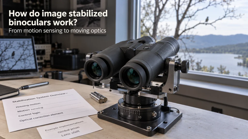
To answer “how do image stabilized binoculars work?” without reducing the mechanism to a marketing label, follow one ordinary hand movement through the binocular. Your hands rotate the housing slightly, a sensor detects that motion, control electronics determine how the optical path should be corrected, and a movable optical component responds. The goal is not to make the binocular body stop moving in your hands. The goal is to keep the viewed scene from moving as much as it would if the optics simply followed every small change in the housing.
That sequence matters because image stabilized binoculars do not all use the same internal architecture even when the outside experience looks similar. Fujifilm and KITE document prism-based gimbal systems, Nikon documents an optical lens-shift method on its current stabilized compact models, and Canon has documented both Vari-Angle Prism and Lens Shift systems in models that it now identifies as discontinued. SIG describes gyroscopically stabilized OIS and different control modes, but its public product material does not need to be stretched into an unsupported claim about exactly which internal element moves. For the broader context of where stabilized designs fit among different types of binoculars, keep the stabilization mechanism separate from prism layout, magnification, objective size, and other optical choices.

This 10x30 binocular uses Canon optical image stabilization in a conventional optical viewing system. Its 30mm objectives and 6-degree real field of view remain separate optical specifications from the stabilizer. Power comes from two AA batteries, making it a clear example of sensing, control, and physical optical correction working together.
Check on AmazonIf you click this link and buy, we earn a commission at no additional cost to you.
Every active system needs sensing, control logic, and an optical correction step
An active optical stabilization loop has three jobs at buyer level: detect motion, decide on a correction, and change the optical path. Manufacturers use different terminology around sensing and control, including electronic gyro sensor, gyro sensor, digital accelerometer, and broader system terms such as gyroscopic stabilization, depending on the model family. The controller then uses that motion information to command the stabilizing mechanism rather than simply recording that the binocular moved. Finally, a movable optical part changes position or orientation so the image seen through the eyepieces is less affected by the motion of the housing.
Those three jobs are more useful than treating a badge such as IS or OIS as a complete mechanical description. A manufacturer may publish detailed information about the sensor and moving prism, or it may explain the control mode while leaving the internal moving component unspecified. That difference in documentation is not proof that one system is better, but it changes what you can responsibly conclude from a spec sheet. When the moving element is not stated, I would leave it unknown rather than borrowing the architecture of another brand and assuming the same mechanism is inside.
- Sensing: detects angular movement or vibration of the binocular body.
- Control: converts the detected movement into a correction command.
- Optical correction: moves or steers an optical element so the viewed image is less affected by that movement.
- Operating limits: determine how much movement the system can correct before the mechanism reaches its usable range.
This framework also prevents a common first-time misunderstanding: electronic control does not automatically mean the binocular is digitally processing a video image. Conventional optical binoculars can use electronics to sense motion and command a physical correction element while the scene still reaches your eyes through the optical path. The electronics control the stabilizer, not a cropped video frame. That distinction becomes especially important when comparing stabilized optical binoculars with camera-based digital binoculars.

This 12x28 model uses Fujifilm electronic gyro stabilization with a gimbal mechanism. The waterproof TS 12x28WP provides up to plus or minus 3 degrees of stabilization correction. It runs on one CR2 lithium battery, so the sensing and correction loop depends on powered control while the product remains an optical binocular.
Check on AmazonIf you click this link and buy, we earn a commission at no additional cost to you.
Fujifilm documents a gyro-sensed gimbal prism in the TECHNO-STABI system
Fujifilm gives a relatively clear mechanism description for its TECHNO-STABI line. The company states that an electronic gyro sensor detects vibration and that an integrated erecting prism is held within a gimbal structure as part of the stabilizing system. In practical terms, the sensor watches the motion of the binocular while the gimbal-mounted prism provides the optical correction that counters part of that movement. That is a specific mechanism claim from the manufacturer, not a template that should be applied to every stabilized binocular.
The buyer-level takeaway is that the sensor and prism have different jobs. The electronic gyro provides motion information, while the movable prism changes the optical path, so saying that “the gyro stabilizes the image” skips the mechanical step that actually redirects the light. This separation also explains why two products can both advertise electronic stabilization yet use different physical correction hardware. If a product page names the sensor but not the moving optic, the correct conclusion is that the sensing method is known while the optical correction element still needs verification.

This 16x28 Techno-Stabi model uses Fujifilm electronic gyro stabilization with a gimbal mechanism. Its stabilization range reaches plus or minus 3 degrees, while 16x magnification and 28mm objectives define the optical configuration. A CR2 lithium battery powers the stabilizing system, separating the active correction hardware from the basic optical specifications.
Check on AmazonIf you click this link and buy, we earn a commission at no additional cost to you.
The moving part and the control behavior vary across manufacturers
The simplest way to compare stabilization technology is to separate architecture from control behavior. Architecture answers what part of the optical system is being steered or shifted, while control behavior answers how the electronics respond to movement and how the user activates or changes the stabilizing mode. A prism on a gimbal, a shifted lens group, and a manufacturer-defined OIS system can all pursue the same practical goal without sharing the same internal mechanism. That is why a generic sentence such as “stabilized binoculars use gyroscopes to move the prisms” is too broad.
The manufacturer map below is useful because it shows both what is documented and what remains unstated. It is not a ranking, and it does not imply that a moving prism is inherently better than a moving lens. The optical result depends on the complete design, the available correction range, control tuning, magnification, and the movement being imposed on the instrument. Use the table to identify which facts you can compare directly before treating two stabilization labels as equivalent.
| Manufacturer example | What is documented | What not to assume |
|---|---|---|
| Fujifilm TECHNO-STABI | Electronic gyro sensing with an erecting prism in a gimbal structure | That every electronic IS system uses the same prism arrangement |
| KITE APC | Prisms suspended on a two-axis gimbal controlled by a gyro sensor | That all gimbal-prism systems share the same correction range or control behavior |
| SIG ZULU6 families | Gyroscopically stabilized OIS with selectable or adaptive control behavior | The exact moving optical element when the public product page does not state it |
| Canon legacy Vari-Angle Prism designs | A Vari-Angle Prism image stabilizer on documented models | That Canon uses the same architecture in every IS binocular |
| Canon legacy Lens Shift designs | A shift-method image stabilizer that moves an IS lens group | That lens shift and Vari-Angle Prism are interchangeable names |
| Nikon STABILIZED compact models | An optical lens-shift method on the documented 10×25 S and 12×25 S | That the same method applies to every Nikon product without model-level verification |
Once the architecture is separated this way, product language becomes easier to read. A control-mode name can describe software behavior without telling you what moves, while a mechanism name can identify the moving element without telling you how aggressively the controller responds. The next step is to read each manufacturer’s documentation at that same level instead of treating every stabilization term as a synonym. That keeps the comparison tied to evidence rather than brand shorthand.
KITE publishes a two-axis gimbal prism controlled by motion sensing
KITE’s APC manual states that the prisms are suspended on a two-axis gimbal mechanism steered by a gyro sensor. That gives a clear signal path: movement is sensed, the stabilizing electronics respond, and the gimbal-mounted prism system supplies the optical correction. KITE also uses Angle Power Control to change the electronics between active and sleep behavior based on the instrument’s orientation, which is a control and power feature rather than a different optical architecture. The useful distinction is that gimbal construction tells you what is being steered, while APC tells you something about when the stabilizing electronics stay active.
SIG describes gyroscopic OIS and control modes without requiring an internal guess
SIG’s ZULU6 documentation describes OIS as gyroscopically stabilized and publishes control behavior such as Scan Mode, Target Mode, and the adaptive OmniScan system on different families. OmniScan uses movement information to vary the degree of stabilization automatically, while other ZULU6 models expose separate user-selectable modes. Those statements are useful for understanding controller behavior, but they do not justify inventing a moving prism or moving lens mechanism when the public page does not name one. For a buyer, the correct comparison is therefore “known control behavior, internal moving element not specified here” rather than forcing SIG into another manufacturer’s architecture.
Canon’s legacy Vari-Angle Prism system shows why brand history can contain more than one mechanism
Canon documents the 10 x 42 L IS WP with a Vari-Angle Prism image stabilizer, and Canon now labels that model discontinued. The value of the page is therefore architectural, not as a current buying recommendation. A Vari-Angle Prism changes the optical path through a deformable prism assembly rather than using the same lens-shift description Canon publishes for some other IS binoculars. This is a good reminder that even within one brand, a familiar IS label does not guarantee one universal moving element.

This 12x36 binocular combines 12x magnification with Canon image stabilization for handheld viewing. The 36mm objectives and other optical specifications remain independent of the stabilization control system. It provides a distinct stabilized implementation to compare with other manufacturers without treating every IS label as the same internal architecture.
Check on AmazonIf you click this link and buy, we earn a commission at no additional cost to you.
Lens-shift systems move a lens group instead of using the same prism architecture
Canon’s documented Lens Shift binoculars provide the cleanest contrast with its Vari-Angle Prism examples. Canon describes models such as the 12 x 32 IS with Lens Shift Image Stabilization and identifies the stabilizer as a shift method, while its explanation of the technology describes the IS lens moving to correct hand shake. Canon now marks that product family as discontinued on its U.S. product pages, so it is better used here to explain a mechanism than to imply current availability. The point is architectural: the correction can be produced by moving a lens group rather than steering a gimbal-mounted prism.
Nikon’s current STABILIZED 10×25 S and 12×25 S add a current example of the same broad mechanism family because Nikon specifies an optical lens-shift method for those models. That does not mean Canon and Nikon use identical sensors, control algorithms, correction travel, or mechanical construction. “Lens shift” identifies the broad optical correction approach, not an industry-standard implementation with fixed performance. When comparing exact models, verify the published mechanism first, then treat correction range, activation behavior, power requirements, and optical specifications as separate questions.

Canon documents this 12x32 model with Lens Shift Image Stabilization and Powered IS control. The stabilizer uses a shift method rather than the same prism architecture found in some other stabilized binocular families. Its 12x magnification and 32mm objectives remain separate optical choices from the lens-shift correction method.
Check on AmazonIf you click this link and buy, we earn a commission at no additional cost to you.
Sensor type and algorithm do not tell you the correction range by themselves
A stabilization system can sense movement correctly and still have a finite amount of optical travel available to counter it. The correction angle describes that operating envelope more directly than a generic stabilization badge, although manufacturers may present the specification differently and exact values must be checked model by model. Large, slow movement and small, rapid hand movement are not the same input, so the correction limit should not be read as a promise that every motion inside a stated angle will look identical. It is simply one important boundary on how far the stabilizing mechanism can compensate before it runs out of usable travel.
This is also why mechanism and correction range belong in separate comparison columns. Fujifilm and KITE both document gimbal-prism approaches, yet that shared architecture does not make their correction limits interchangeable, and lens-shift systems likewise need their own exact-model figures. For a deeper comparison of what those limits mean in use, see how correction angle affects image stabilized binoculars. The practical sequence is to identify the mechanism, verify the correction range for the exact model, and then judge whether that range suits the amount and type of movement you expect.

The TS-X 14x40 combines 14x magnification with a stabilization correction range of up to plus or minus 6 degrees. That published correction range is a separate operating limit from magnification, objective size, and optical quality. The model shows why correction angle should be checked on the exact binocular rather than inferred from a stabilization badge.
Check on AmazonIf you click this link and buy, we earn a commission at no additional cost to you.
The stabilization loop needs power even when the basic optical path still exists
Active stabilization depends on powered sensing and control, so battery behavior is part of the mechanism rather than an unrelated convenience. KITE’s APC documentation, for example, describes electronics that can enter a sleep state depending on the binocular’s orientation, while SIG documents automatic shutoff and mode behavior on its stabilized families. Nikon’s stabilized compact models and the documented Canon IS examples also specify battery-powered stabilization. These details matter because a stabilizer that is not powered cannot keep running its sensing and correction loop.
What happens to the view when power is off still needs exact-model verification. Some optical binoculars can continue to pass a normal unstabilized image because the basic viewing path remains optical, but the manufacturer manual should decide that point rather than a category-wide assumption. Runtime, battery type, sleep behavior, and automatic shutoff are ownership questions that deserve their own comparison once the mechanism is understood. The companion guide to battery life in image stabilized binoculars is the better place to compare those power-management details.

These are 3V CR2 lithium photo batteries in a two-pack. Fujifilm specifies one CR2 lithium battery for the TS 12x28WP and TS 16x28WP stabilization systems, so the battery format matches those models. Keeping the specified battery type available supports the powered sensing and correction loop without changing the binocular optical path.
Check on AmazonIf you click this link and buy, we earn a commission at no additional cost to you.
Stabilization reduces visible motion but does not upgrade the rest of the optical system
A steadier image can make existing detail easier to inspect because the subject moves less within the field, especially as magnification makes hand movement more visible. That does not mean the stabilizer increases objective diameter, changes the exit pupil, adds better coatings, corrects chromatic aberration, widens the field of view, or improves focus precision. Those properties still come from the underlying optical design and exact configuration. Stabilization helps you use the resolution the binocular already delivers more effectively under movement, but it does not manufacture new optical quality after the fact.
This distinction matters when two stabilized models use different magnifications or objective sizes. A higher-magnification stabilized view can show a subject at a larger image scale, but the binocular may still have a narrower field, different eye relief, different low-light behavior, or a different carrying burden. Likewise, a sophisticated control mode cannot compensate for poor physical fit or a focus system that does not suit the way you observe. Treat stabilization as one subsystem in the binocular, not as a replacement for checking the rest of the optical and ergonomic specification.

This 16x42 ZULU6 HDX pairs high magnification with SIG SAUER optical image stabilization. Its 42mm objectives, magnification, field of view, and HDX optical system remain optical design choices that stabilization does not replace. The model illustrates why a steadier image should be evaluated separately from the rest of a binocular optical specification.
Check on AmazonIf you click this link and buy, we earn a commission at no additional cost to you.
Keep optical stabilization separate from digital post-processing
The word “electronic” can cause unnecessary confusion because electronics are used inside optical stabilization systems. In a Fujifilm-style example, an electronic gyro sensor detects movement, but the correction is still made in the optical path by a physical prism mechanism. SIG similarly uses electronic control language around OIS, and Nikon describes optical lens shift on its stabilized compact binoculars. None of those descriptions, by themselves, mean the view is being stabilized by cropping and processing a captured digital video frame.
Digital binoculars can add another layer because a camera sensor, processor, and display may be involved in forming the image the user sees. In that category, post-processing stabilization can be a legitimate separate technique, but it should not be mixed into an explanation of conventional optical IS unless the exact device documents it. The buyer check is simple: determine whether the product presents a direct optical view or an electronically displayed image, then read what the manufacturer says about the correction method. That keeps optical motion correction, sensor-based imaging, and software image processing from being collapsed into one vague idea of electronic stabilization.

The Equinox Z2 uses an infrared-sensitive CMOS sensor to create a digital night-vision image. It can record still images and video up to 1080p and stream live footage over Wi-Fi. That sensor-and-processing workflow makes it a useful contrast case when separating conventional optical image stabilization from digital imaging and post-processing.
Check on AmazonIf you click this link and buy, we earn a commission at no additional cost to you.
Final Thoughts: follow what senses, what moves, and how far it can correct
Image stabilization becomes much easier to compare when you stop at three questions before looking at brand language: what senses the motion, what optical element is moved or steered, and what correction range the exact model publishes. Fujifilm and KITE document gimbal-prism systems, Nikon documents optical lens shift on its stabilized compact models, and Canon’s legacy catalog shows that even one manufacturer can use different architectures across product families. SIG is a useful reminder that a company can publish meaningful control behavior without publicly naming every internal moving component. If the documentation stops there, the accurate answer should stop there too.
That approach also keeps stabilization in proportion. It can reduce visible shake and make handheld viewing more usable, but it does not replace checks for field of view, eye relief, objective size, focus behavior, optical quality, weight, or power requirements. Before comparing two models, verify the mechanism only as far as the manufacturer documents it, then compare correction range and battery behavior separately. The result is a cleaner buying decision because the IS badge no longer has to carry claims that belong to several different subsystems.

This large binocular harness is designed to carry and protect most 50mm and 56mm binoculars. Its padded, weather-resistant construction and adjustable harness support carrying comfort without changing the optics or stabilization system. It is a practical accessory for the weight and fit considerations that still matter after image stabilization is evaluated.
Check on AmazonIf you click this link and buy, we earn a commission at no additional cost to you.
FAQs
🔭 Do all image stabilized binoculars use gyroscopes to move prisms?
No. Fujifilm and KITE document gyro-sensed prism mechanisms, while Nikon documents an optical lens-shift method on its current stabilized compact models. Check the exact product documentation instead of assuming one architecture for the whole category.
⚙️ What actually moves inside image stabilized binoculars?
It depends on the design. The correction element may be a prism system or a lens group, and some manufacturers describe control behavior without publicly naming the moving element.
📐 Does a larger correction angle mean a better stabilizer?
Not by itself. Correction angle tells you about available compensation range, while control behavior, magnification, optical design, and the type of movement still affect the viewing result.
🔋 Will stabilized binoculars work when the batteries are dead?
The active stabilization loop needs power, but passive viewing behavior can differ by model. Check the manual for the exact binocular rather than assuming every optical IS model behaves the same way with stabilization off.
🧠 Is electronic image stabilization the same as digital image processing?
No. Electronics can sense motion and control a physical optical correction element without creating or stabilizing a digital video image. Digital post-processing belongs to a different mechanism and should be verified separately on camera-based binoculars.
👁️ Does stabilization make the glass itself sharper?
No. Stabilization can reduce visible image movement, but optical sharpness, aberration control, coatings, focus quality, and field of view still depend on the binocular’s underlying optical design.
References and Sources
- Fujifilm TECHNO-STABI: documents electronic gyro sensing and an integrated erecting prism in a gimbal structure.
- KITE Optics APC manuals: documents the two-axis gimbal prism mechanism, gyro sensing, activation behavior, and power-control logic used in APC stabilized binoculars.
- SIG SAUER ZULU6: documents gyroscopically stabilized OIS, compensation information, and adaptive OmniScan behavior on current models.
- Nikon STABILIZED binocular series: documents the optical lens-shift method used in the stabilized compact models.
- Canon 10 x 42 L IS WP: documents a legacy Vari-Angle Prism stabilizer and identifies the model as discontinued.
- Canon 12 x 32 IS: documents a legacy Lens Shift Image Stabilization system and identifies the model as discontinued.